Hydraulic Fitting Identification

How to identify hydraulic fittings and ports
NPT Thread

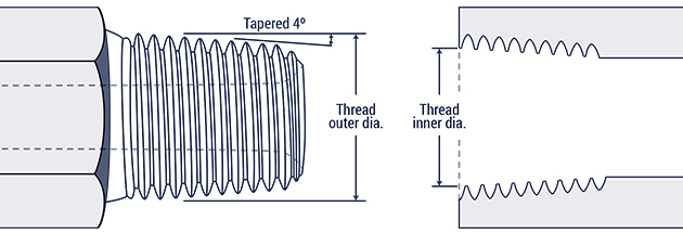
NPTF: National Pipe Tapered Fuel

The seal takes place by deformation of the threads. Thread crests are crushed into mating thread root causing a full metal to metal contact. While it is still used in fluid power, its not recommended as the best option

Dash SizeInch SizeNominal Thread SizeMale Thread O.D. (in.)Female Thread I.D. (in.)
-21/81/8-2713/32 (.41)3/8 (.38)
-41/41/4-1817/32 (.54)1/2″ (.49)
-63/83/8-1811/16 (.68)5/8 (.63)
-81/21/2-1427/32 (.84)25/32 (.77)
-123/43/4-141-1/16 (1.05)1 (.98)
-1611-11 1/21-5/16 (1.32)1-1/4 (1.24)
-201-1/41-1/4 11 1/21-21/32 (1.66)1-19/32 (1.58)
-241-1/21-1/2 11 1/21-29/32 (1.90)1-13/16 (1.82)
-3222 11 1/22-3/8 (2.38)2-5/16 (2.30)
NPSM Thread

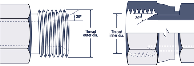
NPSM: National Pipe Straight Mechanical

This connection is sometimes used in fluid power systems. The female half has a straight thread and an inverted 30° seat. The male half of the connection has a straight thread and a 30° internal chamfer. The seal takes place by compression of the 30° seat on the chamfer. The threads hold the connection mechanically. Note: A properly chamfered NPTF male will also seal with the NPSM female.

Dash SizeInch SizeNominal Thread SizeMale Thread O.D. (in.)Female Thread I.D. (in.)
-21/81/8-2713/32 (.41)3/8 (.38)
-41/41/4-1817/32 (.54)1/2″ (.49)
-63/83/8-1811/16 (.68)5/8 (.63)
-81/21/2-1427/32 (.84)25/32 (.77)
-123/43/4-141-1/16 (1.05)1 (.98)
-1611-11 1/21-5/16 (1.32)1-1/4 (1.24)
-201-1/41-1/4 11 1/21-21/32 (1.66)1-19/32 (1.58)
-241-1/21-1/2 11 1/21-29/32 (1.90)1-13/16 (1.82)
-3222 11 1/22-3/8 (2.38)2-5/16 (2.30)

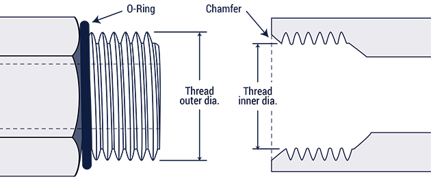
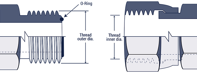
ORB: Straight Thread O-Ring Boss (SAE J1926)

This port connection is recommended by the N.F.P.A. for optimum leakage control in medium and high pressure hydraulic systems. The male connector has a straight thread and an O-Ring. The female port has a straight thread, a machined surface (minimum spotface) and a chamfer to accept the O-Ring. The seal takes place by compressing the O-Ring into the chamfer. The threads hold the connection mechanically.

Dash SizeInch SizeNominal Thread SizeMale Thread O.D. (in.)Female Thread I.D. (in)
-21/85/16-245/16 (.31)9/32 (.27)
-33/163/8-243/8 (.3811/32 (.34)
-41/47/16-207/16 (.44)13/32 (.39)
-55/161/2-201/2 (.50)15/32 (.45)
-63/89/16-189/16 (.56)17/32 (.51)
-81/23/4-163/4 (.75)11/16 (.69)
-105/87/8-147/8 (.88)13/16 (.81)
-123/41 1/16-121-1/16 (1.06)1 (.98)
-147/81 13/16 – 121-3/16 (1.19)1-1/8 (1.10)
-1611 5/16-121- 5/16 (1.31)1-1/4 (1.23)
-201-1/41 5/8-121-5/8 (1.63)1-9/16 (1.54)
-241-1/21 7/8-121-7/8 (1.88)1-13/16 (1.79)
-3222 1/2-122-1/2 (2.5)2-7/16 (2.42)

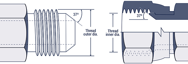
JIC: 37 Degree Hydraulic (SAE J514)

This connection is very common in fluid power systems. Both the male and female halves of the connections have 37° seats. The seal takes place by establishing a line of contact between the male flare and the female cone seat. The threads hold the connection mechanically.
Caution: In the -02, -03, -04, -05, -08 and -10 sizes, the threads of the SAE 37° flare and SAE 45° flare are the same. However, the sealing surface angles are not the same.

Dash SizeInch SizeNominal Thread SizeMale Thread O.D. (in.)Female Thread I.D. (in)
-21/85/16-245/16 (.31)9/32 (.27)
-33/163/8-243/8 (.3811/32 (.34)
-41/47/16-207/16 (.44)13/32 (.39)
-55/161/2-201/2 (.50)15/32 (.45)
-63/89/16-189/16 (.56)17/32 (.51)
-81/23/4-163/4 (.75)11/16 (.69)
-105/87/8-147/8 (.88)13/16 (.81)
-123/41 1/16-121-1/16 (1.06)1 (.98)
-147/81 13/16 – 121-3/16 (1.19)1-1/8 (1.10)
-1611 5/16-121- 5/16 (1.31)1-1/4 (1.23)
-201-1/41 5/8-121-5/8 (1.63)1-9/16 (1.54)
-241-1/21 7/8-121-7/8 (1.88)1-13/16 (1.79)
-3222 1/2-122-1/2 (2.5)2-7/16 (2.42)
SAE 45 Degree Flare

45 Degree Flare (SAE J4512)

This connection is commonly used in refrigeration, automotive and truck piping systems. The connector is frequently made of brass. Both the male and female connectors have 45° seats. The seal takes place between the male flare and the female cone seat. The threads hold the connection mechanically. Caution: In the -02, -03, -04, -05, -08 and -10 sizes, the threads of the SAE 37° flare and SAE 45° flare are the same. However, the sealing surface angles are not the same.

Dash SizeInch SizeNominal Thread SizeMale Thread O.D. (in.)Female Thread I.D. (in)
-21/85/16-245/16 (.31)9/32 (.27)
-33/163/8-243/8 (.3811/32 (.34)
-41/47/16-207/16 (.44)13/32 (.39)
-55/161/2-201/2 (.50)15/32 (.45)
-63/85/8-185/8 (.63)9/16 (.57)
-81/23/4-163/4 (.75)11/16 (.69)
-105/87/8-147/8 (.88)13/16 (.81)
-123/41 1/16-141-1/16 (1.06)1 (.99)
-147/81 1/4 – 121-1/4 (1.25)1-5/32 (1.16)
-1611 3/8 -121-3/8 (1.38)1 9/32 (1.29)
Flareless Tube Fitting

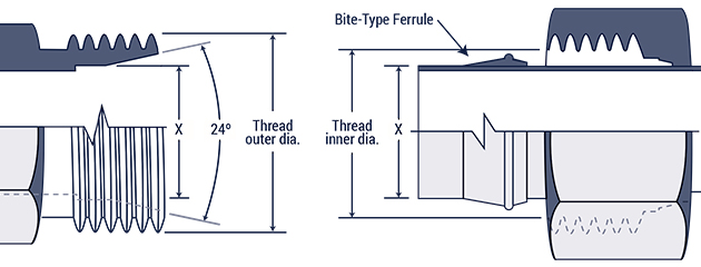
Flareless Tube Fittings (SAE J514)

The male Ermeto connection has straight threads and a 24° seat. The female Ermeto connections incorporates a bite-type sleeve used in conjunction with a tube and female nut. When the female nut is tightened the seal is made between the sleeve and the 24° seat. A seal is also made between the sleeve and the tubing. The threads retain the connection.

Dash SizeInch SizeNominal Thread SizeMale Thread O.D. (in.)Female Thread I.D. (in)
-21/85/16-245/16 (.31)9/32 (.27)
-33/163/8-243/8 (.3811/32 (.34)
-41/47/16-207/16 (.44)13/32 (.39)
-55/161/2-201/2 (.50)15/32 (.45)
-63/89/16-189/16 (.56)17/32 (.51)
-81/23/4-163/4 (.75)11/16 (.69)
-105/87/8-147/8 (.88)13/16 (.81)
-123/41 1/16-121-1/16 (1.06)1 (.98)
-147/81 13/16 – 121-3/16 (1.19)1-1/8 (1.10)
-1611 5/16-121- 5/16 (1.31)1-1/4 (1.23)
-201-1/41 5/8-121-5/8 (1.63)1-9/16 (1.54)
-241-1/21 7/8-121-7/8 (1.88)1-13/16 (1.79)
-3222 1/2-122-1/2 (2.5)2-7/16 (2.42)
O-Ring Face Seal

O-Ring Face Seal (SAE J1453)

This connection offers the very best leakage control available today. The male connector has a straight thread and an O-Ring in the face. The female has a straight thread and a machined flat face. The seal takes place by compressing the O-Ring onto the flat face of the female, similar to the split flange type fitting. The threads hold the connection mechanically.

Dash SizeInch SizeNominal Thread SizeMale Thread O.D. (in.)Female Thread I.D. (in)
-41/49/16-189/16 (.56)17/32 (.51)
-63/811/16-1611/16 (.69)5/8 (.63)
-81/213/16-1613/16 (.82)3/4 (.75)
-105/81-141 (1.00)15/16 (.93)
-123/41 3/16-121-3/16 (1.19)1 1/8 (1.11)
-1611 7/16 -121-7/16 (1.44)1 3/8 (1.36)
-201-1/41 11/16-121 -11/16 (1.69)1 5/8 (1.61)
-241-1/22-122 (2.00)1 15/16 (1.92)
Inverted Flare

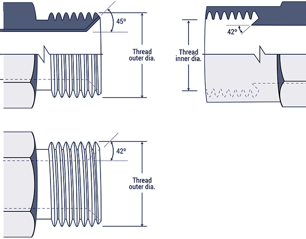
Inverted Flare (SAE J512)

This connection is frequently used in automotive systems. The male connector can either be a 45° flare in the tube fitting form or a 42° seat in the machined adapter form. The female has a straight thread with a 42° inverted flare. The seal takes place on the flared surfaces. The threads hold the connection mechanically.

Dash SizeInch SizeNominal Thread SizeMale Thread O.D. (in.)Female Thread I.D. (in)
-21/85/16-285/16 (.31)9/32 (.27)
-33/163/8-243/8 (.38)11/32 (.34)
-41/47/16-247/16 (.44)13/32 (.40)
-55/161/2-201/2 (.50)15/32 (.45)
-63/85/8-185/8 (.63)9/16 (.57)
-77/1611/16-1811/16 (.69)5/8 (.63)
-81/23/4-183/4 (.75)23/32 (.70)
-105/87/8-187/8 (.88)13/16 (.82)
-123/41 1/16-161-1/16 (1.06)1 (1.00)
4 Bolt Flange

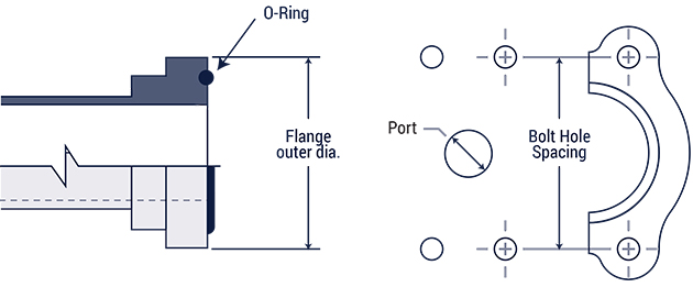
4- Bolt Flange (SAE J518)

This connection is commonly used in fluid power systems. There are two pressure ratings. Code 61 is referred to as the “standard” series and Code 62 is the “6000 psi” series. The design concept for both series is the same, but the bolt hole spacing and flanged head diameters are larger for the higher pressure, Code 62 connection. The female (port) is an unthreaded hole with four bolt holes in a rectangular pattern around the port. The male consists of a flanged head, grooved for an O-Ring, and either a captive flange or split flange halves with bolt holes to match the port. The seal takes place on the O-Ring, which is compressed between the flanged head and the flat surface surrounding the port. The threaded bolts hold the connection together.

Inch Size (Dash Size)Port Hose Bolt I.D.Bolt Dimensions
Bolt Dimensions
Bolt Hole SpacingBolt Hole SpacingFlanged Head DiameterFlanged Head Diameter
Code 61Code 62Code 61Code 62Code 61Code 62
1/2 (08)1/2 (.50)5/16-18 X 1-1/45/16-18 X 1-1/41-1/2 (1.5)1-19/32 (1.60)1-3/16 (1.19)1-1/4 (1.25)
3/4 (12)3/4 (.75)3/8-16 X 1-1/43/8-16 X 1-1/21-7/8 (1.88)2 (2.00)1-1/2 (1.5)1-5/8 (1.63)
1 (16)1 (1.00)3/8-16 X 1-1/47/16-14 X 1-3/42-1/16 (2.06)2-1/4 (2.25)1-3/4 (1.75)1-7/8 (1.88)
1-1/4 (20)1-1/4 ( 1.25)7/16-14 X 1-1/21/2-13 X 1-3/42-5/16 (2.31)2-5/8 (2.63)2 (2.00)2-1/8 (2.13)
1-1/2 (24)1-1/2 (1.5)1/2-13 X 1-1/25/8-11 X 2-1/42-3/4 (2.75)3-1/8 (3.125)2-3/8 (2.38)2-1/2 (2.5)
2 (32)2 (2.00)1/2-13 X 1-1/23/4-10 X 2-3/43-1/16 (3.06)3-13/16 (3.81)2-13/32 (2.81)3-1/8 (3.13)

Note: CAT flanges have a .560” flange thickness (in all sizes) to
correspond Caterpillar® split flanges. Other flange dimensions are
identical to Code 62.